| |
|

|
|
|
|
| |
|

|
| |
 |
Introduction
|
|
|
Every new learner's dream is to understand Verilog in one day, at least enough to use it. The next few pages are my attempt to make this dream a reality. There will be some theory and examples followed by some exercises. This tutorial will not teach you how to program; it is designed for those with some programming experience. Even though Verilog executes different code blocks concurrently as opposed to the sequential execution of most programming languages, there are still many parallels. Some background in digital design is also helpful. |
| |
|

|
|
|
Life before Verilog was a life full of schematics. Every design, regardless of complexity, was designed through schematics. They were difficult to verify and error-prone, resulting in long, tedious development cycles of design, verification... design, verification... design, verification... |
| |
|

|
|
|
When Verilog arrived, we suddenly had a different way of thinking about logic circuits. The Verilog design cycle is more like a traditional programming one, and it is what this tutorial will walk you through. Here's how it goes: |
| |
|

|
|
|
- Specifications (specs)
- High level design
- Low level (micro) design
- RTL coding
- Verification
- Synthesis.
|
| |
|

|
|
|
First on the list is specifications - what are the restrictions and requirements we will place on our design? What are we trying to build? For this tutorial, we'll be building a two agent arbiter: a device that selects among two agents competing for mastership. Here are some specs we might write up. |
| |
|

|
|
|
- Two agent arbiter.
- Active high asynchronous reset.
- Fixed priority, with agent 0 having priority over agent 1
- Grant will be asserted as long as request is asserted.
|
| |
|

|
|
|
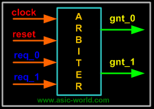
Once we have the specs, we can draw the block diagram, which is basically an abstraction of the data flow through a system (what goes into or comes out of the black boxes?). Since the example that we have taken is a simple one, we can have a block diagram as shown below. We don't worry about what's inside the magical black boxes just yet. |
| |
|

|
| |
 |
Block diagram of arbiter
|
| |
|

|
|
|
 |
| |
|

|
|
|
Now, if we were designing this machine without Verilog, the standard procedure would dictate that we draw a state machine. From there, we'd make a truth table with state transitions for each flip-flop. And after that we'd draw Karnaugh maps, and from K-maps we could get the optimized circuit. This method works just fine for small designs, but with large designs this flow becomes complicated and error prone. This is where Verilog comes in and shows us another way. |
| |
|

|
| |
 |
Low level design
|
|
|
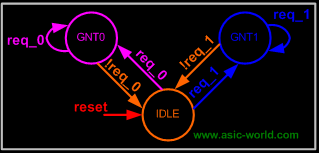
To see how Verilog helps us design our arbiter, let's go on to our state machine - now we're getting into the low-level design and peeling away the cover of the previous diagram's black box to see how our inputs affect the machine. |
| |
|

|
|
|
 |
| |
|

|
|
|
Each of the circles represents a state that the machine can be in. Each state corresponds to an output. The arrows between the states are state transitions, labeled by the event that causes the transition. For instance, the leftmost orange arrow means that if the machine is in state GNT0 (outputting the signal that corresponds to GNT0) and receives an input of !req_0, the machine moves to state IDLE and outputs the signal that corresponds to that. This state machine describes all the logic of the system that you'll need. The next step is to put it all in Verilog. |
| |
|

|
|
|
|
| |
|

|
| |
 |
Modules
|
|
|
We'll need to backtrack a bit to do this. If you look at the arbiter block in the first picture, we can see that it has got a name ("arbiter") and input/output ports (req_0, req_1, gnt_0, and gnt_1). |
| |
|

|
|
|
Since Verilog is a HDL (hardware description language - one used for the conceptual design of integrated circuits), it also needs to have these things. In Verilog, we call our "black boxes" module. This is a reserved word within the program used to refer to things with inputs, outputs, and internal logic workings; they're the rough equivalents of functions with returns in other programming languages. |
| |
|

|
| |
 |
Code of module "arbiter"
|
|
|
If you look closely at the arbiter block we see that there are arrow marks, (incoming for inputs and outgoing for outputs). In Verilog, after we have declared the module name and port names, we can define the direction of each port. (version note: In Verilog 2001 we can define ports and port directions at the same time) The code for this is shown below. |
| |
|

|
|
|
  1 module arbiter (
  2 // Two slashes make a comment line.
  3 clock      , // clock
  4 reset      , // Active high, syn reset
  5 req_0      , // Request 0
  6 req_1      , // Request 1
  7 gnt_0      , // Grant 0
  8 gnt_1        // Grant 1
  9 );
 10 //-------------Input Ports-----------------------------
 11 // Note : all commands are semicolon-delimited
 12 input           clock               ;
 13 input           reset               ;
 14 input           req_0               ;
 15 input           req_1               ;
 16 //-------------Output Ports----------------------------
 17 output        gnt_0                 ;
 18 output        gnt_1                 ;
You could download file one_day1.v here
|
| |
|

|
|
|
Here we have only two types of ports, input and output. In real life, we can have bi-directional ports as well. Verilog allows us to define bi-directional ports as "inout." |
| |
|

|
|
|
Bi-Directional Ports Example - |
| |
|

|
|
|
inout read_enable; // port named read_enable is bi-directional |
| |
|

|
|
|
How do you define vector signals (signals composed of sequences of more than one bit)? Verilog provides a simple way to define these as well. |
| |
|

|
|
|
Vector Signals Example - |
| |
|

|
|
|
inout [7:0] address; //port "address" is bidirectional |
| |
|

|
|
|
Note the [7:0] means we're using the little-endian convention - you start with 0 at the rightmost bit to begin the vector, then move to the left. If we had done [0:7], we would be using the big-endian convention and moving from left to right. Endianness is a purely arbitrary way of deciding which way your data will "read," but does differ between systems, so using the right endianness consistently is important. As an analogy, think of some languages (English) that are written left-to-right (big-endian) versus others (Arabic) written right-to-left (little-endian). Knowing which way the language flows is crucial to being able to read it, but the direction of flow itself was arbitrarily set years back. |
| |
|

|
|
|
Summary |
| |
|

|
|
|
- We learnt how a block/module is defined in Verilog.
- We learnt how to define ports and port directions.
- We learnt how to declare vector/scalar ports.
|
| |
|

|
| |
 |
Data Type
|
|
|
What do data types have to do with hardware? Nothing, actually. People just wanted to write one more language that had data types in it. It's completely gratuitous; there's no point. |
| |
|

|
|
|
But wait... hardware does have two kinds of drivers. |
| |
|

|
|
|
(Drivers? What are those?) |
| |
|

|
|
|
A driver is a data type which can drive a load. Basically, in a physical circuit, a driver would be anything that electrons can move through/into. |
| |
|

|
|
|
- Driver that can store a value (example: flip-flop).
- Driver that can not store value, but connects two points (example: wire).
|
| |
|

|
|
|
The first type of driver is called a reg in Verilog (short for "register"). The second data type is called a wire (for... well, "wire"). You can refer to tidbits section to understand it better. |
| |
|

|
|
|
There are lots of other data types - for instance, registers can be signed, unsigned, floating point... as a newbie, don't worry about them right now. |
| |
|

|
|
|
Examples : |
| |
|

|
|
|
wire and_gate_output; // "and_gate_output" is a wire that only outputs |
|
|
reg d_flip_flop_output; // "d_flip_flop_output" is a register; it stores and outputs a value |
|
|
reg [7:0] address_bus; // "address_bus" is a little-endian 8-bit register |
| |
|

|
|
|
Summary |
| |
|

|
|
|
- Wire data type is used for connecting two points.
- Reg data type is used for storing values.
- May god bless the rest of data types. You'll see them someday.
|
| |
|

|
| |
 |
Operators
|
|
|
Operators, thankfully, are the same things here as they are in other programming languages. They take two values and compare (or otherwise operate on) them to yield a third result - common examples are addition, equals, logical-and... To make life easier for us, nearly all operators (at least the ones in the list below) are exactly the same as their counterparts in the C programming language. |
| |
|

|
|
|
|
Operator Type
|
Operator Symbol
|
Operation Performed
|
|
Arithmetic
|
*
|
Multiply
|
|
|
/
|
Division
|
|
|
+
|
Add
|
|
|
-
|
Subtract
|
|
|
%
|
Modulus
|
|
|
+
|
Unary plus
|
|
|
-
|
Unary minus
|
|
Logical
|
!
|
Logical negation
|
|
|
&&
|
Logical and
|
|
|
||
|
Logical or
|
|
Relational
|
>
|
Greater than
|
|
|
<
|
Less than
|
|
|
>=
|
Greater than or equal
|
|
|
<=
|
Less than or equal
|
|
Equality
|
==
|
Equality
|
|
|
!=
|
inequality
|
|
Reduction
|
~
|
Bitwise negation
|
|
|
~&
|
nand
|
|
|
|
|
or
|
|
|
~|
|
nor
|
|
|
^
|
xor
|
|
|
^~
|
xnor
|
|
|
~^
|
xnor
|
|
Shift
|
>>
|
Right shift
|
|
|
<<
|
Left shift
|
|
Concatenation
|
{ }
|
Concatenation
|
|
Conditional
|
?
|
conditional
|
|
| |
|

|
|
|
Example - |
| |
|

|
|
|
- a = b + c ; // That was very easy
- a = 1 << 5; // Hum let me think, ok shift '1' left by 5 positions.
- a = !b ; // Well does it invert b???
- a = ~b ; // How many times do you want to assign to 'a', it could cause multiple-drivers.
|
|
|
Summary |
| |
|

|
|
|
- Let's attend the C language training again, they're (almost) just like the C ones.
|
| |
|

|
| |
|

|
| |
|

|
|
|
|
| |
|

|