|
|
| |
|

|
|
|
|
| |
|

|
| |
 |
What is logic synthesis ?
|
|
|
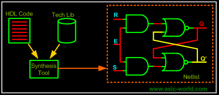
Logic synthesis is the process of converting a high-level description of design into an optimized gate-level representation. Logic synthesis uses a standard cell library which have simple cells, such as basic logic gates like and, or, and nor, or macro cells, such as adder, muxes, memory, and flip-flops. Standard cells put together are called technology library. Normally the technology library is known by the transistor size (0.18u, 90nm). |
| |
|

|
|
|
A circuit description is written in Hardware Description Language (HDL) such as Verilog. The designer should first understand the architectural description. Then he should consider design constraints such as timing, area, testability, and power. |
| |
|

|
|
|
We will see a typical design flow with a large example in the last chapter of Verilog tutorial. |
| |
|

|
|
|
 |
| |
|

|
|
|
|
| |
|

|
| |
 |
Life before HDL (Logic synthesis)
|
|
|
As you must have experienced in college, everything (all the digital circuits) is designed manually. Draw K-maps, optimize the logic, draw the schematic. This is how engineers used to design digital logic circuits in early days. Well this works fine as long as the design is a few hundred gates. |
| |
|

|
| |
 |
Impact of HDL and Logic synthesis.
|
|
|
High-level design is less prone to human error because designs are described at a higher level of abstraction. High-level design is done without significant concern about design constraints. Conversion from high-level design to gates is done by synthesis tools, using various algorithms to optimize the design as a whole. This removes the problem with varied designer styles for the different blocks in the design and suboptimal designs. Logic synthesis tools allow technology independent design. Design reuse is possible for technology-independent descriptions. |
| |
|

|
| |
 |
What do we discuss here ?
|
|
|
When it comes to Verilog, the synthesis flow is the same as for the rest of the languages. What we try to look in next few pages is how particular code gets translated to gates. As you must have wondered while reading earlier chapters, how could this be represented in Hardware ? An example would be "delays". There is no way we could synthesize delays, but of course we can add delay to particular signals by adding buffers. But then this becomes too dependent on synthesis target technology. (More on this in the VLSI section). |
| |
|

|
|
|
First we will look at the constructs that are not supported by synthesis tools; the table below shows the constructs that are not supported by the synthesis tool. |
| |
|

|
| |
|

|
| |
|

|
|
|
|
| |
|

|
|
|
|

|

|

|
|

|
|
Copyright © 1998-2025 |
Deepak Kumar Tala - All rights reserved |
|
Do you have any Comment? mail me at:deepak@asic-world.com
|
|