|
|
| |
|

|
|
|
|
| |
|

|
| |
 |
Gate and Switch delays
|
|
|
In real circuits, logic gates have delays associated with them. Verilog provides the mechanism to associate delays with gates. |
| |
|

|
|
|
- Rise, Fall and Turn-off delays.
- Minimal, Typical, and Maximum delays.
|
| |
|

|
|
|
In Verilog delays can be introduced with #'num' as in the examples below, where # is a special character to introduce delay, and 'num' is the number of ticks simulator should delay current statement execution. |
| |
|

|
|
|
- #1 a = b : Delay by 1, i.e. execute after 1 tick
- #2 not (a,b) : Delay by 2 all assignments made to a.
|
| |
|

|
|
|
Real transistors have resolution delays between the input and output. This is modeled in Verilog by specifying one or more delays for the rise, fall, turn-on and turn off time seperated by commas. |
| |
|

|
|
|
Syntax: keyword #(delay{s}) unique_name (node specifications); |
| |
|

|
|
|
|
Switch element
|
Number Of Delays
|
Specified delays
|
|
Switch
|
1
|
Rise, fall and turn-off times of equal length
|
|
|
2
|
Rise and fall times
|
|
|
3
|
Rise, fall and turn off
|
|
(r)tranif0, (r)tranif1
|
1
|
both turn on and turn off
|
|
|
2
|
turn on, turn off
|
|
(r)tran
|
0
|
None allowed
|
|
| |
|

|
| |
 |
Rise Delay
|
|
|
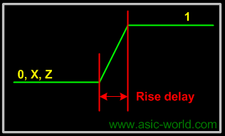
The rise delay is associated with a gate output transition to 1 from another value (0, x, z). |
| |
|

|
|
|
 |
| |
|

|
| |
 |
Fall Delay
|
|
|
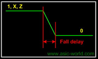
The fall delay is associated with a gate output transition to 0 from another value (1, x, z). |
| |
|

|
|
|
 |
| |
|

|
| |
 |
Turn-off Delay
|
|
|
The Turn-off delay is associated with a gate output transition to z from another value (0, 1, x). |
| |
|

|
| |
 |
Min Value
|
|
|
The min value is the minimum delay value that the gate is expected to have. |
| |
|

|
| |
 |
Typ Value
|
|
|
The typ value is the typical delay value that the gate is expected to have. |
| |
|

|
| |
 |
Max Value
|
|
|
The max value is the maximum delay value that the gate is expected to have. |
| |
|

|
|
|
|
| |
|

|
| |
 |
Example
|
|
|
Below are some examples to show the usage of delays. |
| |
|

|
| |
 |
Example - Single Delay
|
| |
|

|
|
|
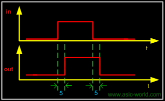
  1 module  buf_gate ();
  2 reg in;
  3 wire out;
  4
  5 buf #(5) (out,in);
  6
  7 initial begin
  8   $monitor ("Time = %g in = %b out=%b", $time, in, out);
  9   in = 0;
 10    #10  in = 1;
 11    #10  in = 0;
 12    #10  $finish;
 13 end
 14
 15 endmodule
You could download file buf_gate.v here
|
| |
|

|
|
|
 Time = 0 in = 0 out=x
 Time = 5 in = 0 out=0
 Time = 10 in = 1 out=0
 Time = 15 in = 1 out=1
 Time = 20 in = 0 out=1
 Time = 25 in = 0 out=0
|
| |
|

|
|
|
 |
| |
|

|
| |
 |
Example - Two Delays
|
| |
|

|
|
|
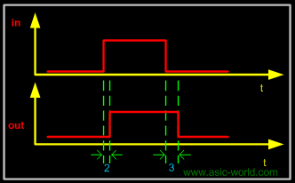
  1 module  buf_gate1 ();
  2 reg in;
  3 wire out;
  4
  5 buf #(2,3) (out,in);
  6
  7 initial begin
  8   $monitor ("Time = %g in = %b out=%b", $time, in, out);
  9   in = 0;
 10    #10  in = 1;
 11    #10  in = 0;
 12    #10  $finish;
 13 end
 14
 15 endmodule
You could download file buf_gate1.v here
|
| |
|

|
|
|
 Time = 0 in = 0 out=x
 Time = 3 in = 0 out=0
 Time = 10 in = 1 out=0
 Time = 12 in = 1 out=1
 Time = 20 in = 0 out=1
 Time = 23 in = 0 out=0
|
| |
|

|
|
|
 |
| |
|

|
| |
 |
Example - All Delays
|
| |
|

|
|
|
  1 module delay();
  2  reg in;
  3  wire rise_delay, fall_delay, all_delay;
  4
  5  initial begin
  6   $monitor (
  7     "Time=%g in=%b rise_delay=%b fall_delay=%b all_delay=%b",
  8     $time, in, rise_delay, fall_delay, all_delay);
  9   in = 0;
 10    #10  in = 1;
 11    #10  in = 0;
 12    #20  $finish;
 13  end
 14
 15  buf #(1,0)U_rise (rise_delay,in);
 16  buf #(0,1)U_fall (fall_delay,in);
 17  buf  #1  U_all (all_delay,in);
 18
 19 endmodule
You could download file delay.v here
|
| |
|

|
|
|
 Time = 0 in = 0 rise_delay = 0 fall_delay = x all_delay = x
 Time = 1 in = 0 rise_delay = 0 fall_delay = 0 all_delay = 0
 Time = 10 in = 1 rise_delay = 0 fall_delay = 1 all_delay = 0
 Time = 11 in = 1 rise_delay = 1 fall_delay = 1 all_delay = 1
 Time = 20 in = 0 rise_delay = 0 fall_delay = 1 all_delay = 1
 Time = 21 in = 0 rise_delay = 0 fall_delay = 0 all_delay = 0
|
| |
|

|
|
|
 |
| |
|

|
| |
 |
Example - Complex Example
|
| |
|

|
|
|
  1 module delay_example();
  2
  3 wire out1,out2,out3,out4,out5,out6;
  4 reg b,c;
  5
  6 // Delay for all transitions
  7 or      #5                    u_or     (out1,b,c);
  8 // Rise and fall delay
  9 and    #(1,2)               u_and    (out2,b,c);
 10 // Rise, fall and turn off delay
 11 nor    #(1,2,3)             u_nor    (out3,b,c);
 12 //One Delay, min, typ and max
 13 nand   #(1:2:3)             u_nand   (out4,b,c);
 14 //Two delays, min,typ and max
 15 buf    #(1:4:8,4:5:6)       u_buf    (out5,b);
 16 //Three delays, min, typ, and max
 17 notif1 #(1:2:3,4:5:6,7:8:9) u_notif1 (out6,b,c);
 18
 19 //Testbench code
 20 initial begin
 21   $monitor (
 22   "Time=%g b=%b c=%b  out1=%b out2=%b out3=%b out4=%b out5=%b out6=%b",
 23     $time, b, c , out1, out2, out3, out4, out5, out6);
 24   b = 0;
 25   c = 0;
 26    #10  b = 1;
 27    #10  c = 1;
 28    #10  b = 0;
 29    #10  $finish;
 30 end
 31
 32 endmodule
You could download file delay_example.v here
|
| |
|

|
|
|
 Time = 0 b = 0 c=0  out1=x out2=x out3=x out4=x out5=x out6=x
 Time = 1 b = 0 c=0  out1=x out2=x out3=1 out4=x out5=x out6=x
 Time = 2 b = 0 c=0  out1=x out2=0 out3=1 out4=1 out5=x out6=z
 Time = 5 b = 0 c=0  out1=0 out2=0 out3=1 out4=1 out5=0 out6=z
 Time = 8 b = 0 c=0  out1=0 out2=0 out3=1 out4=1 out5=0 out6=z
 Time = 10 b = 1 c=0  out1=0 out2=0 out3=1 out4=1 out5=0 out6=z
 Time = 12 b = 1 c=0  out1=0 out2=0 out3=0 out4=1 out5=0 out6=z
 Time = 14 b = 1 c=0  out1=0 out2=0 out3=0 out4=1 out5=1 out6=z
 Time = 15 b = 1 c=0  out1=1 out2=0 out3=0 out4=1 out5=1 out6=z
 Time = 20 b = 1 c=1  out1=1 out2=0 out3=0 out4=1 out5=1 out6=z
 Time = 21 b = 1 c=1  out1=1 out2=1 out3=0 out4=1 out5=1 out6=z
 Time = 22 b = 1 c=1  out1=1 out2=1 out3=0 out4=0 out5=1 out6=z
 Time = 25 b = 1 c=1  out1=1 out2=1 out3=0 out4=0 out5=1 out6=0
 Time = 30 b = 0 c=1  out1=1 out2=1 out3=0 out4=0 out5=1 out6=0
 Time = 32 b = 0 c=1  out1=1 out2=0 out3=0 out4=1 out5=1 out6=1
 Time = 35 b = 0 c=1  out1=1 out2=0 out3=0 out4=1 out5=0 out6=1
|
| |
|

|
| |
 |
N-Input Primitives
|
|
|
The and, nand, or, nor, xor, and xnor primitives have one output and any number of inputs |
| |
|

|
|
|
- The single output is the first terminal.
- All other terminals are inputs.
|
| |
|

|
| |
 |
Examples
|
| |
|

|
|
|
  1 module n_in_primitive();
  2
  3 wire out1,out2,out3;
  4 reg in1,in2,in3,in4;
  5
  6 // Two input AND gate
  7 and u_and1 (out1, in1, in2);
  8 // four input AND gate
  9 and u_and2 (out2, in1, in2, in3, in4);
 10 // three input XNOR gate
 11 xnor u_xnor1 (out3, in1, in2, in3);
 12
 13 //Testbench Code
 14 initial begin
 15   $monitor (
 16   "in1 = %b in2 = %b in3 = %b in4 = %b out1 = %b out2 = %b out3 = %b",
 17   in1, in2, in3, in4, out1, out2, out3);
 18   in1 = 0;
 19   in2 = 0;
 20   in3 = 0;
 21   in4 = 0;
 22    #1  in1 = 1;
 23    #1  in2 = 1;
 24    #1  in3 = 1;
 25    #1  in4 = 1;
 26    #1  $finish;
 27 end
 28
 29 endmodule
You could download file n_in_primitive.v here
|
| |
|

|
|
|
 in1 = 0 in2 = 0 in3 = 0 in4 = 0 out1 = 0 out2 = 0 out3 = 1
 in1 = 1 in2 = 0 in3 = 0 in4 = 0 out1 = 0 out2 = 0 out3 = 0
 in1 = 1 in2 = 1 in3 = 0 in4 = 0 out1 = 1 out2 = 0 out3 = 1
 in1 = 1 in2 = 1 in3 = 1 in4 = 0 out1 = 1 out2 = 0 out3 = 0
 in1 = 1 in2 = 1 in3 = 1 in4 = 1 out1 = 1 out2 = 1 out3 = 0
|
| |
|

|
| |
|

|
| |
 |
N-Output Primitives
|
|
|
The buf and not primitives have any number of outputs and one input |
| |
|

|
|
|
- The outputs are the first terminals listed.
- The last terminal is the single input.
|
| |
|

|
| |
 |
Examples
|
| |
|

|
|
|
  1 module n_out_primitive();
  2
  3 wire out,out_0,out_1,out_2,out_3,out_a,out_b,out_c;
  4 wire in;
  5
  6 // one output Buffer gate
  7 buf u_buf0 (out,in);
  8 // four output Buffer gate
  9 buf u_buf1 (out_0, out_1, out_2, out_3, in);
 10 // three output Invertor gate
 11 not u_not0 (out_a, out_b, out_c, in);
 12
 13 endmodule
You could download file n_out_primitive.v here
|
| |
|

|
| |
|

|
| |
|

|
|
|
|
| |
|

|
|
|