|
|
| |
|

|
|
|
|
| |
|

|
| |
 |
Introduction
|
|
|
If you refer to any book on programming languages, it starts with an "Hello World" program; once you have written it, you can be sure that you can do something in that language  . . |
| |
|

|
|
|
Well I am also going to show how to write a "hello world" program, followed by a "counter" design, in Verilog. |
| |
|

|
| |
 |
Hello World Program
|
| |
|

|
|
|
  1 //-----------------------------------------------------
  2 // This is my first Verilog Program
  3 // Design Name : hello_world
  4 // File Name : hello_world.v
  5 // Function : This program will print 'hello world'
  6 // Coder    : Deepak
  7 //-----------------------------------------------------
  8 module hello_world ;
  9
 10 initial begin
 11   $display ("Hello World by Deepak");
 12    #10  $finish;
 13 end
 14
 15 endmodule // End of Module hello_world
You could download file hello_world.v here
|
| |
|

|
|
|
Words in green are comments, blue are reserved words. Any program in Verilog starts with reserved word 'module' <module_name>. In the above example line 8 contains module hello_world. (Note: We can have compiler pre-processor statements like `include', `define' before module declaration) |
| |
|

|
|
|
Line 10 contains the initial block: this block gets executed only once after the simulation starts, at time=0 (0ns). This block contains two statements which are enclosed within begin, at line 10, and end, at line 13. In Verilog, if you have multiple lines within a block, you need to use begin and end. Module ends with 'endmodule' reserved word, in this case at line 15. |
| |
|

|
| |
 |
Hello World Program Output
|
| |
|

|
|
|
Hello World by Deepak
|
| |
|

|
|
|
|
| |
|

|
| |
 |
Counter Design Block
|
| |
|

|
|
|
 |
| |
|

|
| |
 |
Counter Design Specs
|
| |
|

|
|
|
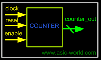
- 4-bit synchronous up counter.
- active high, synchronous reset.
- Active high enable.
|
| |
|

|
| |
 |
Counter Design
|
| |
|

|
|
|
  1 //-----------------------------------------------------
  2 // This is my second Verilog Design
  3 // Design Name : first_counter
  4 // File Name : first_counter.v
  5 // Function : This is a 4 bit up-counter with
  6 // Synchronous active high reset and
  7 // with active high enable signal
  8 //-----------------------------------------------------
  9 module first_counter (
 10 clock , // Clock input of the design
 11 reset , // active high, synchronous Reset input
 12 enable , // Active high enable signal for counter
 13 counter_out // 4 bit vector output of the counter
 14 ); // End of port list
 15 //-------------Input Ports-----------------------------
 16 input clock ;
 17 input reset ;
 18 input enable ;
 19 //-------------Output Ports----------------------------
 20 output [3:0] counter_out ;
 21 //-------------Input ports Data Type-------------------
 22 // By rule all the input ports should be wires
 23 wire clock ;
 24 wire reset ;
 25 wire enable ;
 26 //-------------Output Ports Data Type------------------
 27 // Output port can be a storage element (reg) or a wire
 28 reg [3:0] counter_out ;
 29
 30 //------------Code Starts Here-------------------------
 31 // Since this counter is a positive edge trigged one,
 32 // We trigger the below block with respect to positive
 33 // edge of the clock.
 34 always @ (posedge clock)
 35 begin : COUNTER // Block Name
 36   // At every rising edge of clock we check if reset is active
 37   // If active, we load the counter output with 4'b0000
 38   if (reset == 1'b1) begin
 39     counter_out <=  #1  4'b0000;
 40   end
 41   // If enable is active, then we increment the counter
 42   else if (enable == 1'b1) begin
 43     counter_out <=  #1  counter_out + 1;
 44   end
 45 end // End of Block COUNTER
 46
 47 endmodule // End of Module counter
You could download file first_counter.v here
|
| |
|

|
| |
 |
Counter Test Bench
|
|
|
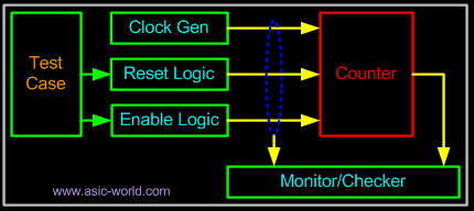
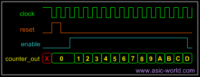
Any digital circuit, no matter how complex, needs to be tested. For the counter logic, we need to provide clock and reset logic. Once the counter is out of reset, we toggle the enable input to the counter, and check the waveform to see if the counter is counting correctly. This is done in Verilog. |
| |
|

|
|
|
 |
| |
|

|
|
|
The counter testbench consists of clock generator, reset control, enable control and monitor/checker logic. Below is the simple code of testbench without the monitor/checker logic. |
| |
|

|
|
|
  1 `include "first_counter.v"
  2 module first_counter_tb();
  3 // Declare inputs as regs and outputs as wires
  4 reg clock, reset, enable;
  5 wire [3:0] counter_out;
  6
  7 // Initialize all variables
  8 initial begin
  9   $display ("time\t clk reset enable counter");
 10   $monitor ("%g\t %b   %b     %b      %b",
 11 	  $time, clock, reset, enable, counter_out);
 12   clock = 1;       // initial value of clock
 13   reset = 0;       // initial value of reset
 14   enable = 0;      // initial value of enable
 15    #5  reset = 1;    // Assert the reset
 16    #10  reset = 0;   // De-assert the reset
 17    #10  enable = 1;  // Assert enable
 18    #100  enable = 0; // De-assert enable
 19    #5  $finish;      // Terminate simulation
 20 end
 21
 22 // Clock generator
 23 always begin
 24    #5  clock = ~clock; // Toggle clock every 5 ticks
 25 end
 26
 27 // Connect DUT to test bench
 28 first_counter U_counter (
 29 clock,
 30 reset,
 31 enable,
 32 counter_out
 33 );
 34
 35 endmodule
You could download file first_counter_tb.v here
|
| |
|

|
|
|
 time     clk reset enable counter
 0        1   0     0      xxxx
 5        0   1     0      xxxx
 10       1   1     0      xxxx
 11       1   1     0      0000
 15       0   0     0      0000
 20       1   0     0      0000
 25       0   0     1      0000
 30       1   0     1      0000
 31       1   0     1      0001
 35       0   0     1      0001
 40       1   0     1      0001
 41       1   0     1      0010
 45       0   0     1      0010
 50       1   0     1      0010
 51       1   0     1      0011
 55       0   0     1      0011
 60       1   0     1      0011
 61       1   0     1      0100
 65       0   0     1      0100
 70       1   0     1      0100
 71       1   0     1      0101
 75       0   0     1      0101
 80       1   0     1      0101
 81       1   0     1      0110
 85       0   0     1      0110
 90       1   0     1      0110
 91       1   0     1      0111
 95       0   0     1      0111
 100      1   0     1      0111
 101      1   0     1      1000
 105      0   0     1      1000
 110      1   0     1      1000
 111      1   0     1      1001
 115      0   0     1      1001
 120      1   0     1      1001
 121      1   0     1      1010
 125      0   0     0      1010
|
| |
|

|
| |
 |
Counter Waveform
|
| |
|

|
|
|
 |
| |
|

|
| |
|

|
| |
|

|
|
|
|
| |
|

|
|
|
|

|

|

|
|

|
|
Copyright © 1998-2025 |
Deepak Kumar Tala - All rights reserved |
|
Do you have any Comment? mail me at:deepak@asic-world.com
|
|