|
|
| |
|

|
|
|
|
| |
|

|
| |
 |
Introduction
|
|
|
Writing a testbench is as complex as writing the RTL code itself. These days ASICs are getting more and more complex and thus verifying these complex ASIC has become a challenge. Typically 60-70% of time needed for any ASIC is spent on verification/validation/testing. Even though the above facts are well known to most ASIC engineers, still engineers think that there is no glory in verification. |
| |
|

|
|
|
I have picked up some examples from the VLSI classes that I used to teach during 1999-2001, when I was in Chennai. Please feel free to give your feedback on how to improve the tutorial below. |
| |
|

|
| |
 |
Before you Start
|
|
|
For writing testbenches it is important to have the design specification of "design under test" or simply DUT. Specs need to be understood clearly and a test plan, which basically documents the test bench architecture and the test scenarios (test cases) in detail, needs to be made. |
| |
|

|
|
|
|
| |
|

|
| |
 |
Example - Counter
|
|
|
Let's assume that we have to verify a simple 4-bit up counter, which increments its count whenever enable is high, and resets to zero when reset is asserted high. Reset is synchronous to clock. |
| |
|

|
| |
 |
Code for Counter
|
| |
|

|
|
|
  1 //-----------------------------------------------------
  2 // Design Name : counter
  3 // File Name   : counter.v
  4 // Function    : 4 bit up counter
  5 // Coder       : Deepak
  6 //-----------------------------------------------------
  7 module counter (clk, reset, enable, count);
  8 input clk, reset, enable;
  9 output [3:0] count;
 10 reg [3:0] count;
 11
 12 always @ (posedge clk)
 13 if (reset == 1'b1) begin
 14   count <= 0;
 15 end else if ( enable == 1'b1) begin
 16   count <= count + 1;
 17 end
 18
 19 endmodule
You could download file counter.v here
|
| |
|

|
| |
 |
Test Plan
|
|
|
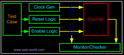
We will write a self-checking test bench, but we will do this in steps to help you understand the concept of writing automated test benches. Our testbench environment will look something like the figure below. |
| |
|

|
|
|
 |
| |
|

|
|
|
DUT is instantiated in the testbench, and the testbench will contain a clock generator, reset generator, enable logic generator and compare logic, which basically calculates the expected count value of counter and compares it with the output of counter. |
| |
|

|
| |
 |
Test Cases
|
| |
|

|
|
|
- Reset Test : We can start with reset de-asserted, followed by asserting reset for few clock ticks and deasserting the reset, See if counter sets its output to zero.
- Enable Test : Assert/deassert enable after reset is applied.
- Random Assert/deassert of enable and reset.
|
| |
|

|
|
|
We can add some more test cases; but we are not here to test the counter, rather to learn how to write test benches. |
| |
|

|
| |
|

|
| |
|

|
|
|
|
| |
|

|
|
|
|

|

|

|
|

|
|
Copyright © 1998-2025 |
Deepak Kumar Tala - All rights reserved |
|
Do you have any Comment? mail me at:deepak@asic-world.com
|
|