|
|
| |
|

|
|
|
|
| |
|
|
|
|
Note : This section was written by Avidan Efody (avidan_e@yahoo.com). You are more than welcome to send comments, complaints, corrections or tempting work offers to Avidan Efody.
|
| |
|
|
| |
 |
A Specman Testbench
|
|
|
This chapter describes the basic division of a Specman testbench into functional blocks.
|
| |
|
|
| |
 |
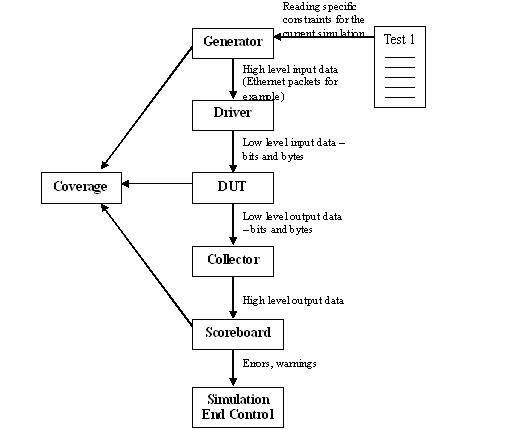
Diagram of a basic testbench
|
|
|
 |
| |
|
|
|
|
The above figure shows the main logical parts of a testbench (by logical I mean that they do not necessarily correspond to the actual files or units in your verification testbench).
|
| |
|
|
| |
|
The Generator and the Test
|
|
|
The Generator is supposed to be able to generate all the possible correct input data to your chip and also some interesting erroneous data structures. For example, if your chip is supposed to handle Ethernet packets, your generator should be able to generate Ethernet packets of every legal length (64 bytes to 1500 bytes) and every legal combination of data (as mentioned before, usually the fields in a packet are related to each other in some way, so your generator must make sure that these rules are respected). Also, your generator should be able to generate some possible erroneous data for example, Ethernet packets that are smaller or larger in size, or that contain a field where the data is corrupted. While testing your chip with problematic data you should always have the protocol standard and the specification for your own chip at a hand's reach. Otherwise, you might find yourself coping with some totally imaginary exotic errors, that no chip will ever be able to handle. In such cases you should limit yourself to making sure that the system does not crash.
|
| |
|
|
|
|
If your generator is well thought it will be able to generate, as mentioned above, every possible kind of data. However, normally you would like to restrict your data to specific cases: Either because your Verilog or VHDL code is not finished yet and you would like to check only the completed parts in your design, or you would like to direct your testbench to a specific interesting case whose chances of happening naturally are slim, or a costumer reports a bug and you would like to reconstruct it in your verification environment. Whatever the reason is, this is the role of the Test. The test contains additional constraints (using extensions as shown above), whose purpose is to direct the generation to a specific area. After a while you might find yourself with quite a lot of different tests, some of which are quite useless, since they fail to find any bugs. Coverage might help you select the best tests but this is only a limited solution, since it is based on a self defined criteria, and not on the number of actual bugs found (more below).
|
| |
|
|
| |
|
The Driver
|
|
|
After the data is generated it should be injected to the DUT. This is the task of the Driver. The driver gets the high level’ data, for example a complete Ethernet packet, and converts it into low level data, which is usually a list of bits, bytes etc. In other words, the driver is responsible for implementing the physical level protocol (request to send, wait two clock cycles, acknowledge, and all this hardware bullshit if you have an electrical engineer in your team, this is the job you should assign him with J). In order to transform the high level data (packets) into low level data (a list of bits) E provides you with a method called pack() (which is very similar to serialize in C++). This method, innocent to the unsuspecting eye, is the second cause of suicides among E beginners, the first being the generation debugger. Do not be tempted to combine the generator with the driver. Verisity support engineers insist that this dividing line should be kept, and in this case they are definitely right: The physical level interfaces of an ASIC can change very often (widespread changes include change in pins names, removing or adding pins, turning single purpose pins into multifunctional pins etc), while the high level data formats are more or less fixed. For obvious reasons of code reuse, you do not want to touch one of the most sensible parts in your E code (the generation) whenever the physical interface changes.
|
| |
|
|
|
|
|
| |
|
|
| |
|
The Collector
|
| |
|
|
|
|
The Collector, at the other side of the DUT (i.e your Verilog or VHDL code), is the inverse of the driver. Here you use the method “unpack()” to turn the low level data into high level structures, while losing whatever is left of your sanity. Everything else is more or less the same as the driver.
|
| |
|
|
| |
|
The Scoreboard
|
|
|
Once the data is arranged into high level structures, it is handed over to the Scoreboard, which is the most complicated part of every testbench, even a Verilog or a C one. The main role of the scoreboard is of course to check that the output data is correct, that it came out on time and as expected. Unlike the random generation, where one can immediately see the advantages of E over directed verification methods, in the parts where the data is checked, E is more or less just like its predecessors, which explains why Verisity salesman will always take a generator for their demonstrations.
|
| |
|
|
|
|
Since E definitely does not revolutionize the world of data checking, the methods for building a scoreboard with E are similar to those used before. The best way to go is to have separate design and verification teams, whose only medium of communication is a specification that was written by someone else. Writing this specification is the most difficult part and once it is written, it should be clear that any requests to change it (usually from the design team) are not welcome. Working like this guarantees that your scoreboard will not turn into a carbon copy of the chip/block and therefore eliminates the risk of having the same bug in both the scoreboard and the chip/block. Also, cloning a block in a scoreboard is a gruesome task, which you should do your best to avoid. However, so far I have not seen this model in real life – usually because the specification is not good enough, goes into too much detail, or was written by the design team (!! - a stupid mistake that makes the specification totally useless except for documentation).
|
| |
|
|
|
|
Sometimes the nature of your design allows you to make important shortcuts. For example, communication chips are normally two-way, transmitting and receiving data at the same time. In this case, you could use the transmitter to check the receiver, and hence simplify the scoreboard considerably, since it will only have to make sure that the transmitted data is back. Another way for making things easier is to use some kind of pseudo random data, instead of using totally random data – for example, incremental data in an Ethernet packet. When using random data, you have to keep a record of all the data that was transmitted in order to check it at the other end. Incremental data or any other foreknown sequence makes the scoreboard totally independent of the generator. In other words, while random data usually means that the generator inserts data into some shared data base and the scoreboard takes it out, with pseudo random data this is obviously unnecessary. Usually, you build your generator in such a way that it can generate either random or pseudo random data, and use a boolean variable with a constraint in your test file to control the generation. Finally, for better reuse sanity checks on data should not be located at the scoreboard, but instead be included as methods of the data items themselves. For example, checking that the number of data bytes in a packet corresponds to the value in the length field should be done by a method of the packet structure and not by the scoreboard.
|
| |
|
|
|
|
Most projects proceed like this: the chip is divided into blocks, the blocks are coded into Verilog or VHDL, tested separately using Specman, then reintegrated and tested end to end. Therefore, most major blocks, will have a dedicated testbench (including all the elements shown in the figure above). Even after integration, these dedicated testbenchs retain an important role (so keep them updated and run them every once in a while). First, when a bug is detected in a specific block during integration, it might be a lot faster to get to the bottom of it and fix it using the dedicated environment. Second, the scoreboards and collectors of all blocks might be used in the end to end tests, alongside an end to end scoreboard. True, simulation with several scoreboards might go a bit slower, but this will pay off because most bugs will be discovered earlier, and will be a lot easier to debug. In some cases, when an end to end scoreboard is too complex to build, a chain of scoreboards on internal blocks is a reasonable replacement, despite its obvious shortcomings.
|
| |
|
|
| |
|
Simulation End Control
|
|
|
The block named Simulation End Control in the diagram above is an example of Verisity's neglect in addressing methodological issues (see more below). While the other blocks in the diagram (generator, driver, collector, scoreboard, coverage) are all a part of Verisity's basic methodology, this block is my own humble contribution. It is supposed to answer a simple question: when should the simulation end? A famous rule says that every simulation, without exception, has to end at one point or another. Which of the five parts in Verisity's scheme (generator, driver, collector, scoreboard, coverage) is responsible for this task? None. The result of this omission is that the end of the simulation can come from almost everywhere, and sometimes it indeed does: a limit on the number of generated items in the generator, a time limit in the simulator, a limit on the elements checked by a scoreboard, or when any of the scoreboards reports an error. It is enough to call the method dut_error() or stop_run() from anywhere in the code, to stop the simulation. To me it seems that it makes more sense to have one piece of code that decides when a test should end, since this would make it obviously much easier to change the criteria dynamically. This is especially true when you have several scoreboards operating in a single environment and you would like to ignore the errors originating in one of them (which means you should try to avoid using the method dut_error()). Or, you would like to end the test according to an algorithm which takes into account the number of data items checked by the scoreboard, the simulation time, and maybe the actual duration of the run. Also, controlling the end of the simulation from a centralized location, helps to integrate code from different writers.
|
| |
|
|
|
|
Bear in mind that a bug discovered after several hours of simulation is not a useful bug, since trying to fix it would cost too much time. Its not enough to find a bug, you also have to find it at the shortest verification time possible. So, controlling the end of a simulation is in fact equivalent to specifying the maximal amount of time you are ready to “pay” for a bug.
|
| |
|
|
| |
|
Coverage
|
|
|
The last block in our testbench is responsible for Coverage. There are two main types of coverage. Input coverage should check if the generator is in fact generating all the types of data that one expects it to generate. For example, to check if an E model of a 8086 program RAM is generating all the available assembler commends. Input coverage should be taken seriously because of a curious behavior of Specman when its generator fails to generate a certain combination, due to a true or imagined contradiction in your constraints, it will sometimes just generate an easier type of data without bothering to share this crucial information with you. Output coverage is there in order to tell you if you have in fact tested all the parts that you wanted to test in your design. In other words, when the output coverage is 100% you can send your design to the ASIC vendor and start packing for a vacation in Hawaii. The output coverage should be based on a detailed document, written after the specification by the same writer, then passed over to the design engineer, who should look as best as he can for the weakest spots in his design and suggest how they are to be tested. There might be situations that seem to need testing, and yet, are very difficult to detect from the outside of the block or the chip. A good example of this are state machines, where you should check the behavior of your code in all states, but these states, are hardly visible from the outside. Therefore, output coverage is usually collected both from the outside, using the scoreboard in order to identify specific interesting situations, and from the inside, either by spying on internal signals, such as state machine registers, or in an end to end simulation, by relying on internal scoreboards.
|
| |
|
|
| |
|
A few words on methodology
|
|
|
In conclusion to this section a few, somewhat abstract words on methodology might be in place. Verisity offers one way for building a testbench: all testbenchs should include a generator, a driver, a collector, a scoreboard and coverage (as mentioned above, the block called Simulation End Control, is my own invention and is not a part of Verisity’s methodology). As far as Verisity is concerned, no matter if you are designing a 8086 or a Pentium 5, your testbench will look just the same except for the scale. Whether building a CPU core or an Ethernet Mac, whether at the very start of your project or already approaching the end, your testbench will be more or less identical. In software projects, choosing the right methodology is one of the heaviest decisions and its implication are quite well felt, especially when the projects undergo changes (such as data base or algorithm replacement). It is my impression that Verisity, in a smart move, prefers to distract the attention of its potential clients from the real burning issues of methodology, by presenting them with a simple magic solution, whose shortcomings they will discover only after they are already deeply involved with Specman and E. I have already given one example of this above with the Simulation End Control block. What follows are a few other examples and a lesson to be learned from all of them.
|
| |
|
|
|
|
First, the methodology Verisity offers does not refer to the natural development of a project: what should one do with the dedicated verification environments that were written at the beginning as the project advances? This is one of the most painful questions since in a large project, you might have as many as 20 separate environments or more, each with its own generator and scoreboard. As mentioned above, these environments can be helpful, but this depends very much on how they are written. For example, if in a dedicated environment the scoreboard relies on the generator, it will be useless in an end to end environment from which all dedicated generators are removed. Another example: scoreboards comprise at least 60% of the E code you will write, but apart from the very general notion that your testbench should include a scoreboard, Verisity offers almost no clues as to how scoreboards should be built or how they should be adapted to common types of DUTs (CPUs, communication chips etc). Or yet another example: most dedicated generators have some common parts with other generators but Verisity’s methodology, which is suited only to the verification of a single block does not draw a line between the general parts and the specific parts of a generator. Of course, you might say that anyone who is not clever enough to draw such a line by himself deserves some extra work. This, however, only precludes my own recommendation: you should give serious thought to methodology and structure and avoid taking Verisity’s somewhat simplistic schemes as given. You will be surprised to find out that some people, in search for a magic solution, do.
|
| |
|
|
| |
|
|
| |
|
|
|
|
|
| |
|
|
|
|