| |
|

|
|
|
|
| |
|

|
| |
 |
Boolean Function Implementation
|
|
|
Earlier we had seen that it is possible to implement Boolean functions using decoders. In the same way it is also possible to implement Boolean functions using muxers and de-muxers. |
| |
|

|
| |
 |
Implementing Functions Multiplexers
|
|
|
Any n-variable logic function can be implemented using a smaller 2n-1-to-1 multiplexer and a single inverter (e.g 4-to-1 mux to implement 3 variable functions) as follows. |
| |
|

|
|
|
Express function in canonical sum-of-minterms form. Choose n-1 variables as inputs to mux select lines. Construct the truth table for the function, but grouping inputs by selection line values (i.e select lines as most significant inputs). |
|
|
Determine multiplexer input line i values by comparing the remaining input variable and the function F for the corresponding selection lines value i. |
| |
|

|
|
|
We have four possible mux input line i values: |
| |
|

|
|
|
- Connect to 0 if the function is 0 for both values of remaining variable.
- Connect to 1 if the function is 1 for both values of remaining variable.
- Connect to remaining variable if function is equal to the remaining variable.
- Connect to the inverted remaining variable if the function is equal to the remaining variable inverted.
|
| |
|

|
|
|
|
| |
|

|
| |
 |
Example: 3-variable Function Using 8-to-1 mux
|
|
|
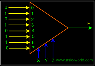
Implement the function F(X,Y,Z) = S(1,3,5,6) using an 8-to-1 mux. Connect the input variables X, Y, Z to mux select lines. Mux data input lines 1, 3, 5, 6 that correspond to the function minterms are connected to 1. The remaining mux data input lines 0, 2, 4, 7 are connected to 0. |
| |
|

|
|
|
 |
| |
|

|
| |
 |
Example: 3-variable Function Using 4-to-1 mux
|
|
|
Implement the function F(X,Y,Z) = S(0,1,3,6) using a single 4-to-1 mux and an inverter. We choose the two most significant inputs X, Y as mux select lines. |
|
|
Construct truth table. |
| |
|

|
|
|
Truth Table |
|
|
|
Select i
|
X
|
Y
|
Z
|
F
|
Mux Input i
|
|
0
|
0
|
0
|
0
|
1
|
1
|
|
0
|
0
|
0
|
1
|
1
|
1
|
|
1
|
0
|
1
|
0
|
0
|
Z
|
|
1
|
0
|
1
|
1
|
1
|
Z
|
|
2
|
1
|
0
|
0
|
0
|
0
|
|
2
|
1
|
0
|
1
|
0
|
0
|
|
3
|
1
|
1
|
0
|
1
|
Z'
|
|
3
|
1
|
1
|
1
|
0
|
Z'
|
|
| |
|

|
|
|
Circuit |
| |
|

|
|
|
 |
| |
|

|
|
|
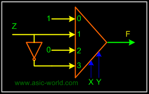
We determine multiplexer input line i values by comparing the remaining input variable Z and the function F for the corresponding selection lines value i |
| |
|

|
|
|
- when XY=00 the function F is 1 (for both Z=0, Z=1) thus mux input0 = 1
- when XY=01 the function F is Z thus mux input1 = Z
- when XY=10 the function F is 0 (for both Z=0, Z=1) thus mux input2 = 0
- when XY=11 the function F is Z' thus mux input3 = Z'
|
| |
|

|
| |
 |
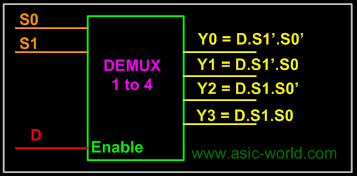
Example: 2 to 4 Decoder using Demux
|
| |
|

|
|
|
 |
| |
|

|
| |
 |
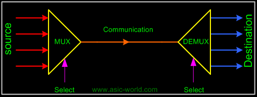
Mux-Demux Application Example
|
|
|
This enables sharing a single communication line among a number of devices. At any time, only one source and one destination can use the communication line. |
| |
|

|
|
|
 |
| |
|

|
| |
|

|
| |
|

|
|
|
|
| |
|

|