|
|
| |
|

|
|
|
|
| |
|

|
| |
 |
Introduction
|
|
|
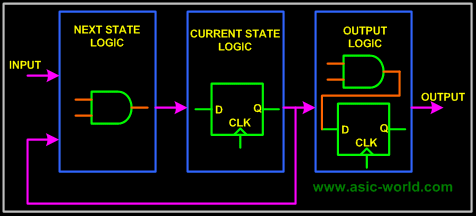
Basically a FSM consists of combinational, sequential and output logic. Combinational logic is used to decide the next state of the FSM, sequential logic is used to store the current state of the FSM. The output logic is a mixture of both combo and seq logic as shown in the figure below. |
| |
|

|
|
|
 |
| |
|

|
|
|
Types of State Machines |
|
|
There are many ways to code these state machines, but before we get into the coding styles, let's first understand the basics a bit. There are two types of state machines: |
| |
|

|
|
|
- Mealy State Machine : Its output depends on current state and current inputs. In the above picture, the blue dotted line makes the circuit a mealy state machine.
- Moore State Machine : Its output depends on current state only. In the above picture, when blue dotted line is removed the circuit becomes a Moore state machine.
|
|
|
Depending on the need, we can choose the type of state machine. In general, or you can say most of the time, we end up using Mealy FSM. |
| |
|

|
|
|
Encoding Style |
|
|
Since we need to represent the state machine in a digital circuit, we need to represent each state in one of the following ways: |
| |
|

|
|
|
- Binary encoding : each state is represented in binary code (i.e. 000, 001, 010....)
- Gray encoding : each state is represented in gray code (i.e. 000, 001, 011,...)
- One Hot : only one bit is high and the rest are low (i.e. 0001, 0010, 0100, 1000)
- One Cold : only one bit is low, the rest are high (i.e. 1110,1101,1011,0111)
|
|
|
Most of the time we use one hot encoding. |
| |
|

|
|
|
Example |
| |
|

|
|
|
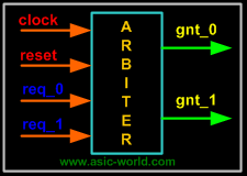
To help you follow the tutorial, I have taken a simple arbiter as the example; this has got two request inputs and two grant outputs, as shown in the signal diagram below. |
| |
|

|
|
|
- When req_0 is asserted, gnt_0 is asserted
- When req_1 is asserted, gnt_1 is asserted
- When both req_0 and req_1 are asserted then gnt_0 is asserted i.e. higher priority is given to req_0 over req_1.
|
| |
|

|
|
|
 |
| |
|

|
|
|
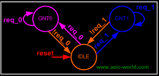
We can symbolically translate into a FSM diagram as shown in figure below, here FSM has got following states. |
| |
|

|
|
|
- IDLE : In this state FSM waits for the assertion of req_0 or req_1 and drives both gnt_0 and gnt_1 to inactive state (low). This is the default state of the FSM, it is entered after the reset and also during fault recovery condition.
- GNT0 : FSM enters this state when req_0 is asserted, and remains here as long as req_0 is asserted. When req_0 is de-asserted, FSM returns to the IDLE state.
- GNT1 : FSM enters this state when req_1 is asserted, and remains there as long as req_1 is asserted. When req_1 is de-asserted, FSM returns to the IDLE state.
|
| |
|

|
|
|
 |
| |
|

|
|
|
Coding Methods |
| |
|

|
|
|
Now that we have described our state machine clearly, let's look at various methods of coding a FSM. |
| |
|

|
|
|
We use one-hot encoding, and all the FSMs will have the following code in common, so it will not be repeated again and again. |
| |
|

|
| |
|

|
|
|
|
| |
|

|
| |
 |
Using A Function For Combo Logic
|
| |
|

|
|
|
  1 //-----------------------------------------------------
  2 // This is FSM demo program using function
  3 // Design Name : fsm_using_function
  4 // File Name   : fsm_using_function.v
  5 //-----------------------------------------------------
  6 module fsm_using_function (
  7 clock      , // clock
  8 reset      , // Active high, syn reset
  9 req_0      , // Request 0
 10 req_1      , // Request 1
 11 gnt_0      , // Grant 0
 12 gnt_1
 13 );
 14 //-------------Input Ports-----------------------------
 15 input   clock,reset,req_0,req_1;
 16  //-------------Output Ports----------------------------
 17 output  gnt_0,gnt_1;
 18 //-------------Input ports Data Type-------------------
 19 wire    clock,reset,req_0,req_1;
 20 //-------------Output Ports Data Type------------------
 21 reg     gnt_0,gnt_1;
 22 //-------------Internal Constants--------------------------
 23 parameter SIZE = 3           ;
 24 parameter IDLE  = 3'b001,GNT0 = 3'b010,GNT1 = 3'b100 ;
 25 //-------------Internal Variables---------------------------
 26 reg   [SIZE-1:0]          state        ;// Seq part of the FSM
 27 wire  [SIZE-1:0]          next_state   ;// combo part of FSM
 28 //----------Code startes Here------------------------
 29 assign next_state = fsm_function(state, req_0, req_1);
 30 //----------Function for Combo Logic-----------------
 31 function [SIZE-1:0] fsm_function;
 32   input  [SIZE-1:0]  state ;
 33   input    req_0 ;
 34   input    req_1 ;
 35   case(state)
 36    IDLE : if (req_0 == 1'b1) begin
 37                 fsm_function = GNT0;
 38               end else if (req_1 == 1'b1) begin
 39                 fsm_function= GNT1;
 40               end else begin
 41                 fsm_function = IDLE;
 42               end
 43    GNT0 : if (req_0 == 1'b1) begin
 44                 fsm_function = GNT0;
 45               end else begin
 46                 fsm_function = IDLE;
 47               end
 48    GNT1 : if (req_1 == 1'b1) begin
 49                 fsm_function = GNT1;
 50           end else begin
 51                 fsm_function = IDLE;
 52               end
 53    default : fsm_function = IDLE;
 54   endcase
 55 endfunction
 56 //----------Seq Logic-----------------------------
 57 always @ (posedge clock)
 58 begin : FSM_SEQ
 59   if (reset == 1'b1) begin
 60     state <=  #1  IDLE;
 61   end else begin
 62     state <=  #1  next_state;
 63   end
 64 end
 65 //----------Output Logic-----------------------------
 66 always @ (posedge clock)
 67 begin : OUTPUT_LOGIC
 68 if (reset == 1'b1) begin
 69   gnt_0 <=  #1  1'b0;
 70   gnt_1 <=  #1  1'b0;
 71 end
 72 else begin
 73   case(state)
 74     IDLE : begin
 75                   gnt_0 <=  #1  1'b0;
 76                   gnt_1 <=  #1  1'b0;
 77                end
 78    GNT0 : begin
 79                    gnt_0 <=  #1  1'b1;
 80                    gnt_1 <=  #1  1'b0;
 81                 end
 82    GNT1 : begin
 83                    gnt_0 <=  #1  1'b0;
 84                    gnt_1 <=  #1  1'b1;
 85                 end
 86    default : begin
 87                     gnt_0 <=  #1  1'b0;
 88                     gnt_1 <=  #1  1'b0;
 89                   end
 90   endcase
 91 end
 92 end // End Of Block OUTPUT_LOGIC
 93
 94 endmodule // End of Module arbiter
You could download file fsm_using_function.v here
|
| |
|

|
| |
 |
Using Two Always Blocks
|
| |
|

|
|
|
  1 //-----------------------------------------------------
  2 // This is FSM demo program using always block
  3 // Design Name : fsm_using_always
  4 // File Name   : fsm_using_always.v
  5 //-----------------------------------------------------
  6 module fsm_using_always (
  7 clock      , // clock
  8 reset      , // Active high, syn reset
  9 req_0      , // Request 0
 10 req_1      , // Request 1
 11 gnt_0      , // Grant 0
 12 gnt_1
 13 );
 14 //-------------Input Ports-----------------------------
 15 input   clock,reset,req_0,req_1;
 16  //-------------Output Ports----------------------------
 17 output  gnt_0,gnt_1;
 18 //-------------Input ports Data Type-------------------
 19 wire    clock,reset,req_0,req_1;
 20 //-------------Output Ports Data Type------------------
 21 reg     gnt_0,gnt_1;
 22 //-------------Internal Constants--------------------------
 23 parameter SIZE = 3           ;
 24 parameter IDLE  = 3'b001,GNT0 = 3'b010,GNT1 = 3'b100 ;
 25 //-------------Internal Variables---------------------------
 26 reg   [SIZE-1:0]          state        ;// Seq part of the FSM
 27 reg   [SIZE-1:0]          next_state   ;// combo part of FSM
 28 //----------Code startes Here------------------------
 29 always @ (state or req_0 or req_1)
 30 begin : FSM_COMBO
 31  next_state = 3'b000;
 32  case(state)
 33    IDLE : if (req_0 == 1'b1) begin
 34                 next_state = GNT0;
 35               end else if (req_1 == 1'b1) begin
 36                 next_state= GNT1;
 37               end else begin
 38                 next_state = IDLE;
 39               end
 40    GNT0 : if (req_0 == 1'b1) begin
 41                 next_state = GNT0;
 42               end else begin
 43                 next_state = IDLE;
 44               end
 45    GNT1 : if (req_1 == 1'b1) begin
 46                 next_state = GNT1;
 47               end else begin
 48                 next_state = IDLE;
 49               end
 50    default : next_state = IDLE;
 51   endcase
 52 end
 53 //----------Seq Logic-----------------------------
 54 always @ (posedge clock)
 55 begin : FSM_SEQ
 56   if (reset == 1'b1) begin
 57     state <=  #1  IDLE;
 58   end else begin
 59     state <=  #1  next_state;
 60   end
 61 end
 62 //----------Output Logic-----------------------------
 63 always @ (posedge clock)
 64 begin : OUTPUT_LOGIC
 65 if (reset == 1'b1) begin
 66   gnt_0 <=  #1  1'b0;
 67   gnt_1 <=  #1  1'b0;
 68 end
 69 else begin
 70   case(state)
 71     IDLE : begin
 72                   gnt_0 <=  #1  1'b0;
 73                   gnt_1 <=  #1  1'b0;
 74                end
 75    GNT0 : begin
 76                    gnt_0 <=  #1  1'b1;
 77                    gnt_1 <=  #1  1'b0;
 78                 end
 79    GNT1 : begin
 80                    gnt_0 <=  #1  1'b0;
 81                    gnt_1 <=  #1  1'b1;
 82                 end
 83    default : begin
 84                     gnt_0 <=  #1  1'b0;
 85                     gnt_1 <=  #1  1'b0;
 86                   end
 87   endcase
 88 end
 89 end // End Of Block OUTPUT_LOGIC
 90
 91 endmodule // End of Module arbiter
You could download file fsm_using_always.v here
|
| |
|

|
| |
 |
Using Single Always For Sequential, Combo And Output Logic
|
| |
|

|
|
|
  1 //====================================================
  2 // This is FSM demo program using single always
  3 // for both seq and combo logic
  4 // Design Name : fsm_using_single_always
  5 // File Name   : fsm_using_single_always.v
  6 //=====================================================
  7 module fsm_using_single_always (
  8 clock      , // clock
  9 reset      , // Active high, syn reset
 10 req_0      , // Request 0
 11 req_1      , // Request 1
 12 gnt_0      , // Grant 0
 13 gnt_1
 14 );
 15 //=============Input Ports=============================
 16 input   clock,reset,req_0,req_1;
 17  //=============Output Ports===========================
 18 output  gnt_0,gnt_1;
 19 //=============Input ports Data Type===================
 20 wire    clock,reset,req_0,req_1;
 21 //=============Output Ports Data Type==================
 22 reg     gnt_0,gnt_1;
 23 //=============Internal Constants======================
 24 parameter SIZE = 3           ;
 25 parameter IDLE  = 3'b001,GNT0 = 3'b010,GNT1 = 3'b100 ;
 26 //=============Internal Variables======================
 27 reg   [SIZE-1:0]          state        ;// Seq part of the FSM
 28 reg   [SIZE-1:0]          next_state   ;// combo part of FSM
 29 //==========Code startes Here==========================
 30 always @ (posedge clock)
 31 begin : FSM
 32 if (reset == 1'b1) begin
 33   state <=  #1  IDLE;
 34   gnt_0 <= 0;
 35   gnt_1 <= 0;
 36 end else
 37  case(state)
 38    IDLE : if (req_0 == 1'b1) begin
 39                 state <=  #1  GNT0;
 40                 gnt_0 <= 1;
 41               end else if (req_1 == 1'b1) begin
 42                 gnt_1 <= 1;
 43                 state <=  #1  GNT1;
 44               end else begin
 45                 state <=  #1  IDLE;
 46               end
 47    GNT0 : if (req_0 == 1'b1) begin
 48                 state <=  #1  GNT0;
 49               end else begin
 50                 gnt_0 <= 0;
 51                 state <=  #1  IDLE;
 52               end
 53    GNT1 : if (req_1 == 1'b1) begin
 54                 state <=  #1  GNT1;
 55               end else begin
 56                 gnt_1 <= 0;
 57                 state <=  #1  IDLE;
 58               end
 59    default : state <=  #1  IDLE;
 60 endcase
 61 end
 62
 63 endmodule // End of Module arbiter
You could download file fsm_using_single_always.v here
|
| |
|

|
| |
|

|
| |
|

|
|
|
|
| |
|

|
|
|
|